

TM 9-2350-222-20-1-4
MASTER CONTROL PANEL REPAIR (Sheet 26 of 65)
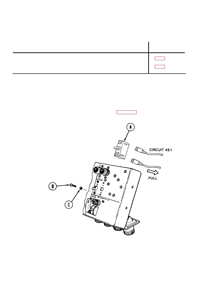
Bilge Pump Switch and Indicator Light Replacement (Sheet 1 of 4)
PROCEDURE INDEX
PROCEDURE
PAGE
Removal
Installation
TOOLS: 4 in. cross-tip screwdriver
10 in. adjustable wrench
1 in. combination box and open end wrench
SUPPLIES: Silicone compound (Item 32, Appendix D)
Preformed packing (MS28775-119)
Lockwasher (MS35338-42) (4 required)
PRELIMINARY PROCEDURE:
Remove panel from vehicle (page 10-48)
REMOVAL:
1.
Using fingers, remove two electrical connectors
from rear of switch (A) by pulling out.
2.
Using screwdriver, remove two screws (B) and
lockwashers (C) securing switch (A) to panel.
Throw lockwashers away.
3.
Remove switch (A).
Go on to Sheet 2
TA139636
10-80

