

TM 9-2350-222-20-1-4
P A R K I N G BRAKE CONTROL ASSEMBLY REPLACEMENT (ENGINE MOUNTED)
(Sheet 6 of 7)
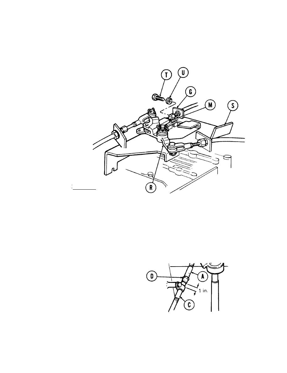
11. Position connector (M) in bellcrank assembly (R). Using a 9/16 inch socket and extension, install
bracket (G) to bracket assembly (S) with two screws (T) and new lockwashers (U).
CAUTION
Make sure control assembly (C) is secured
to hull wall with clamp located on metal
casing, one inch below disconnect nut (D).
12. Using adjustable wrench on flats of control assembly (A), and torque wrench with 7/8 inch crowfoot,
tighten disconnect nut (D) to 35-50 lb-in (8.9 to 12.7 N.m).
TA253455
Go on to Sheet 7
13-98.6 Change 1

