

TM9-2350-222-20-1-3
FUEL-WATER SEPARATOR OPERATIONAL TESTS (2D ENGINE) (Sheet 3 of 11)
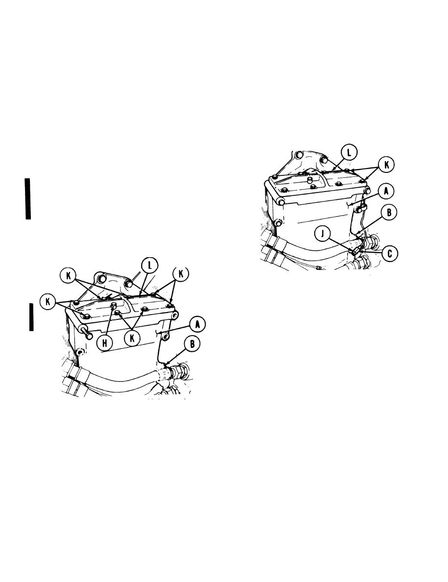
Using 1/2 inch wrench, remove sensor retaining nut (J).
11.
Using adjustable wrench, install pipe plug into lower sensor probe (C) hole.
12.
If fuel did not leak from upper sensor (B) hole, use adjustable wrench to remove pipe plug from
13.
upper sensor (B) hole and go to step 14. If fuel did leak from upper sensor (B) hole, go to step 18.
Using 7/16 inch wrench, remove eight screws, lockwashers, and flat washers (K) securing cover (L) to
14.
separator (A). Remove cover (L) from separator (A). Throw lockwashers away.
CAUTION
There is a gasket located between
and
cover
separator
fuel-water
fuel-water separator body. To avoid fuel
leaks, each time cover is removed, care
must be taken not to disturb gasket.
15. Add fuel to fuel-water separator (A) until fuel
leaks from upper sensor (B) hole.
16. Using adjustable wrench, install pipe plug in
upper sensor (B) hole.
Place cover (L) in position and, using 7/16
17.
inch wrench, install eight screws, new lock-
washers, and flat washers (K).
Using 1/2 inch wrench, open bleed cap H) by
18.
turning counterclockwise.
Place metal container (M) under out et of
19.
manual drain valve (N).
20. Open manual drain valve (N) by turning
petcock (P) counterclockwise. Allow small
amount of fluid to drain into metal container
(M), and then close manual drain valve (N).
21. If fluid does not drain, refer to troubleshooting
procedure (page 4-1).
22. If fluid does drain, go on to automatic drain test
on next page.
Go on to Sheet 4
TA253213
7-268 Change 1

