

TM9-2350-222-20-1-3
FUEL PUMP REPLACEMENT - LEFT FUEL TANK (Sheet 1 of 9)
PROCEDURE INDEX
PROCEDURE
PAGE
Removal
Installation
1/4 in. combination box and open end wrench
TOOLS:
1/2 in. combination box and open end wrench
1/2 in. socket with 3/8 in. drive
Ratchet with 3/8 in. drive
Diagonal cutting pliers
Torque wrench with 3/8 in. drive (0-200 lb-in) (0-23 Nm)
Slip joint pliers
Flat-tip screwdriver
SUPPLIES:
Lockwire (Item 60, Appendix D)
Gasket (10873918)
Lockwasher (MS35333-38) (2 required)
Lockwasher (MS45904-72)
Lockwasher (MS35338-44) (4 required)
REFERENCE:
TM 9-2350-222-10
PRELIMINARY PROCEDURES:
Isolate left fuel tank (TM 9-2350-222-10)
Drain left fuel tank (page 7-152)
Remove powerplant (page 5-1) .
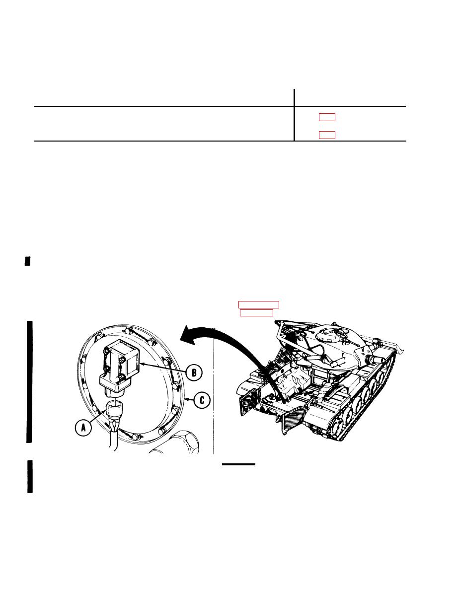
CAUTION
REMOVAL:
When powerplant is removed for any reason, note position of electrical
lead (A). Turn capacitor and housing assembly (B), if necessary, so lead
(A) enters from below.
1.
Using hands, unplug electrical lead (A) from capacitor and housing assembly (B) located on fuel
pump access cover (C).
Go on to Sheet 2
TA253194
7-52 Change 1

