

TM 9-2350-222-20-2-3-2
DIRECT VISION WINDOW INSTALLATION PROCEDURE
36-59.
7/8 in. socket (3/8 in. drive)
TOOLS:
6 in. extension (3/8 in. drive)
3/8 in. drive torque wrench (0 to 50 foot pounds)
Plastic faced hammer
Long nose pliers
Lockwire (wedge type installation only)
SUPPLIES:
Retainer (11655057) (two) (for retainer type installation only)
Sealing compound (item 16, App. A)
PERSONNEL: One
EQUIPMENT LOCATION INFORMATION:
FOLDOUT
CALLOUT
EQUIPMENT
11
Driver's Master Control Panel
Driver's master control panel MASTER BATTERY switch set to OFF
EQUIPMENT CONDITION:
FRAME 1
Procedure
Step
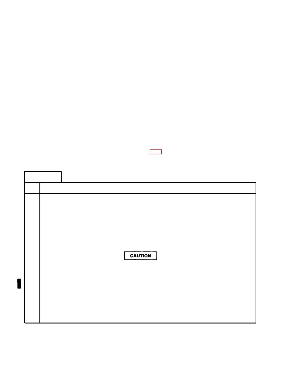
NOTE
This frame is for wedge type installation. Go to frame 2 for retainer
type installation.
Put sealing compound on frame area (1).
1.
Put wedge (2) and direct vision window (3) into frame area (l).
2.
3.
Put two screws (4) in wedge (2) mounting holes. Tighten finger tight.
Take care in tightening screws to keep from cracking direct vision
window.
4.
Using torque wrench, torque two screws (4) between 7 and 10 foot pounds (9 and 14 Newton meters).
5.
Using pliers, put lockwire (5) on screws (4).
6.
After sealing compound has dried, check that direct vision window (3) is water tight.
END OF TASK
Para 36-59
36-138
Change 2
