

TM 9-2350-222-20-1-3
POWERPLANT REPLACEMENT (2D ENGINE) (Sheet 17 of 23)
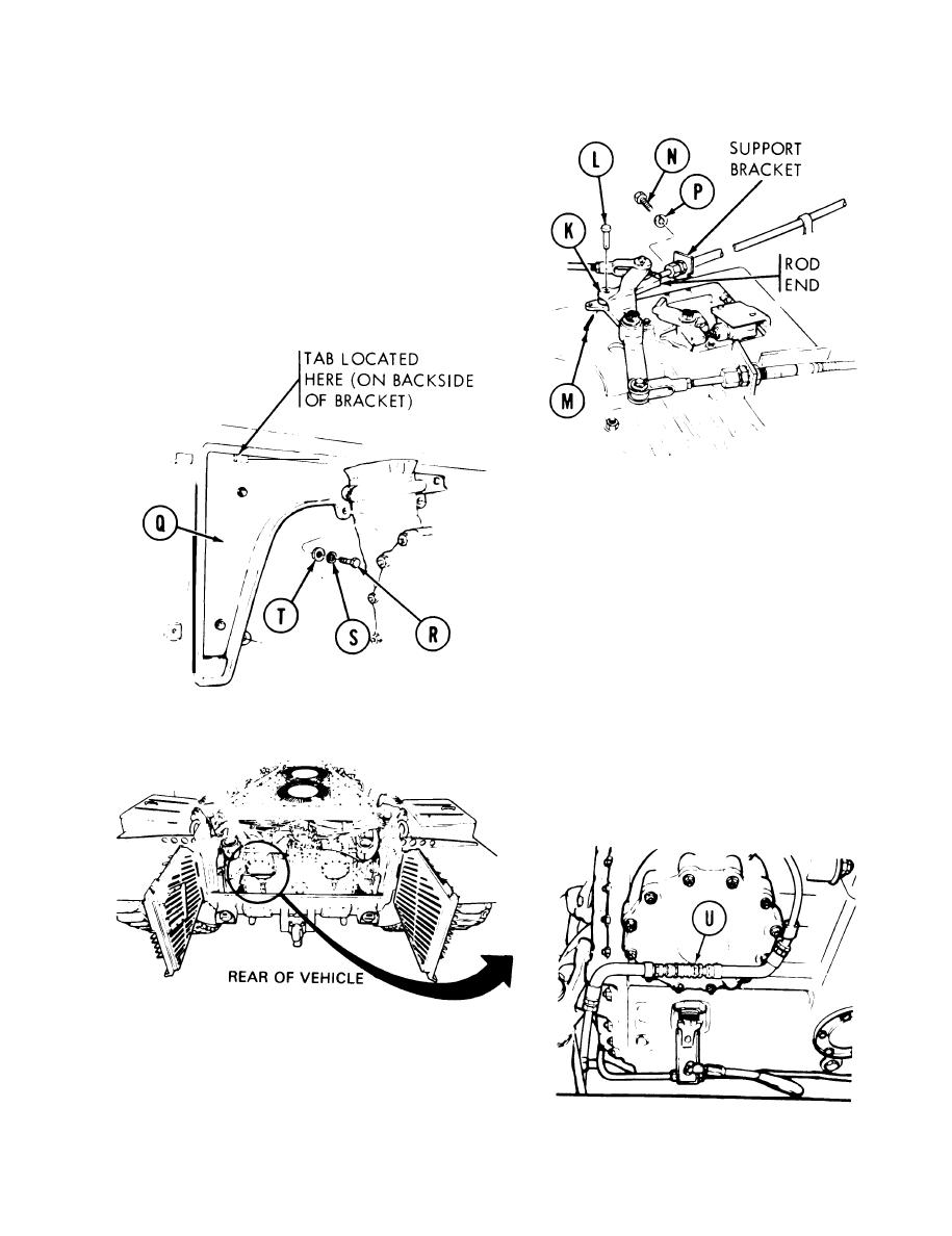
23. Position rod end of parking brake control into
bellcrank (K).
24. Manually install straight pin (L).
25. Using pliers, install cotter pin (M).
26. Using 9/16 inch socket, install two screws (N)
and Iockwashers (P) to hold parking brake
support bracket.
27.
Position angle brackets (Q) to rear side walls
(by powerplant guides). Hang tab of brackets
onto tabs on compartment side walls.
28.
Manually start three screws (R), lockwashers
(S), and washers (T) to hold angle bracket (Q)
to side walls.
29.
Using 9/16 inch socket with 2 inch extension,
tighten three screws (R) to secure angle
brackets (Q) to side walls.
30.
Remove protective coverings from fuel return
line openings.
31.
Manually connect fuel return line by pulling
back on quick-disconnect fitting (U) and
inserting male connector into female
connector.
Go on to Sheet 18
5-41
Change 4
