TM
5-5420-226-20-1
Svmr)tom-69
DETAILED
TROUBLESHOOTING
PROCEDURE
+
SUPPORT
SYSTEM
- VEHICLE
LIGHTING
L
(Continued)
Check
master
control
panel accessories
harness
(CKT 514-51 5) at panel connector
for electrical
Dower.
First
l
l
l
l
l
l
l
l
Technician
(Operator’s
Station)
Install
foot DIMMER
SWITCH
(page
10-170).
Set B.O. SELECTOR
switch
to IR.
Displace
master
control
panel
(page
10-33).
Disconnect
basket-control
panel
accessories
harness
connector
from
master
control
panel.
Set multimeter
to measure
18 to 30 volts dc or use STE/
ICE Test
No.
89 (page
4-81).
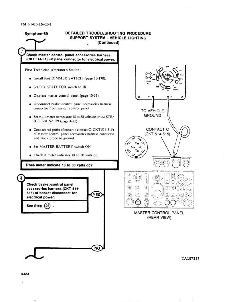
Connect
red probe of meter to contact
C(CKT
514-5
15)
of master
control
panel
accessories
harness
connector
and black
probe
to ground.
Set MASTER
BATTERY
switch
ON.
Check
if meter
indicates
18 to 30 volts dc,
Does meter
indicate
18 to 30 volts dc?
)
Check
basket-control
panel
accessories
harness
(CKT 514-
515) at basket
disconnect
for
electrical
power.
See Step
@
.
0YES
TO VEHICLE
GROUND
CONTACT
c
—
MASTER
CONTROL
PANEL
(REAR VIEW)
TA107353
4-664


