TM
5-5420-226-20-1
Symptom-47
DETAILED
TROUBLESHOOTING
PROCEDURE
INDICATOR
- LAMP
T’
(Continued)
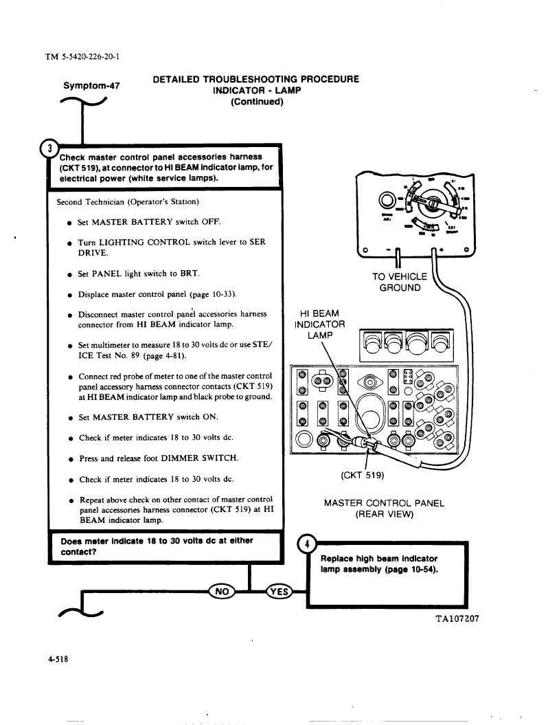
Check
master
control
panel accessories
harness
(CKT 519), at connector
to HI BEAM indicator
lamp, for
electrical
power
(white
service
lamps).
Second
Technician
(Operator’s
Station)
l Set MASTER
BATTERY
switch
OFF.
l Turn LIGHTING
CONTROL
switch
lever to SER
DRIVE.
l Set PANEL
light switch
to BRT.
l Displace
master
control
panel
(page
10-33).
l Disconnect
master
control
panel
accessories
harness
connector
from
HI BEAM
indicator
lamp.
l Set multimeter
to measure
18 to 30 volts dc or use STE/
ICE Test
No.
89 (page
4-81).
l Connect red probe of meter to one of the master control
panel accessory
harness
connector
contacts
(CKT
519)
at HI BEAM
indicator
lamp and black probe to ground.
l Set MASTER
BATTERY
switch
ON.
l Check if meter indicates
18 to 30 volts dc.
l Press and release foot DIMMER
SWITCH.
l Check if meter indicates
18 to 30 volts dc.
l Repeat above check on other contact of master control
panel
accessories
harness
connector
(CKT
5 19) at HI
BEAM
indicator
lamp.
4
Does meter
indicate
18 to 30 volts dc at either
contact?
m
\
HI BEAM
INDICATOR
LAMP
\
l
0.9
n,
o
-n
n +
o
Ii
TO VEHICLE
GROUND
mm
MASTER
CONTROL
PANEL
(REAR
VIEW)
‘1’Replacehigh beam Indicator
lamp assembly
(page
10-54).
I
TA1072O7
4-518
,>