TM 5-5420-226-20-1
Symptom-35
DETAILED
TROUBLESHOOTING
PROCEDURE
INDICATOR
- GAGE
Transmission
oil must cool before
proceeding.
(Continued)
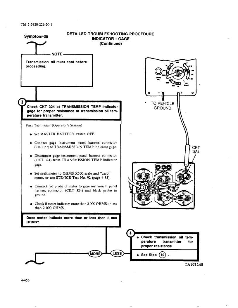
Check
CKT
324 at TRANSMISSION
TEMP
indicator
gage for proper
resistance
of transmission
oil tem-
perature
transmitter.
Firs[
l
l
l
l
l
l
Technician
(Operator’s
Station)
Set MASTER
BATTERY
switch
OFF.
Connect
gage
instrument
panel
harness
connector
(CKT
27) to TRANSMISSION
TEMP
indicator
gage.
Disconnect
gage
instrument
panel
harness
connector
(CKT
324) from
TRANSMISSION
TEMP
indicator
gage.
Set multimeter
to OHMS
X100
scale and
“zero”
meter,
or use STE/ICE
Test
No. 92 (page
4-83).
Connect
red probe
of meter
to gage instrument
panel
harness
connector
(CKT
324)
and
black
probe
to
ground.
Check if meter indicates
more than 2000 OHMS
or less
than
2000
OHMS.
Does
meter
indicate
more
than or less than
2
000
OHMS?
I
o
-n
+
o
M
II
“
TO VEHICLE
1!
GROUND
\
CKT
324
*
o
l See Step
10
4-456
TA107145

