TM 5-5420-226-20-1
DETAiLED
TROUBLESHOOTING
PROCEDURE
INDICATOR
- GAGE
(Continued)
Symptom-34
~
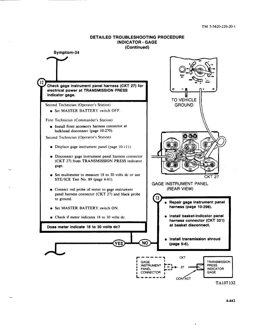
Check gage instrument
panel harness
(CKT 27) for
electrical
power
at TRANSMISSION
PRESS
indicator
gage.
Second
Technician
(Operator’s
Station)
l Set MASTER
BATTERY
switch
OFF.
First
Technician
(Commander’s
Station)
l Install front accessory
harness
connector
at
bulkhead
disconnect
(page
10-270).
Second
Technician
(Operator’s
Station)
l Displace
gage instrument
panel
(page
10-111).
l Disconnect
gage instrument
panel
harness
connector
(CKT
27) from
TRANSMISSION
PRESS
indicator
gage.
l Set multimeter
to measure
18 to 30 volts dc or use
STE/ICE
Test
No.
89 (page
4-81).
l Connect
red probe
of meter
to gage instrument
panel
harness
connector
(CKT
27) and black
probe
to ground.
l Set MASTER
BATTERY
switch
ON.
l Check if meter indicates
18 to 30 volts dc.
/
Does meter indicate
18 to 30 volts dc?
\
n
o
-,n
+
o
TO VEHICLE
GROUND
II
CKT 27
GAGE
INSTRUMENT
PANEL
(REAR
VIEW)
(
)l Repair gage instrumentpanel
harness
(page
10-298).
l Install basket-indicator
panel
harness
connector
(CKT 321)
at basket
disconnect.
l Install transmission
shroud
(page 9-6).
loNO
r
-----
1
CKT
#
GAGE
#
i
INSTRUMENT
b-i
<
TRANSMISSION
I
H r-.
27
PRESS
:
PANEL
-.
INDICATOR
I
CONNECTOR
~
/
GAGE
L
----.-
a
CONTACT
TA107132
.—
4-443