.
TM 5-5420-226-20-1
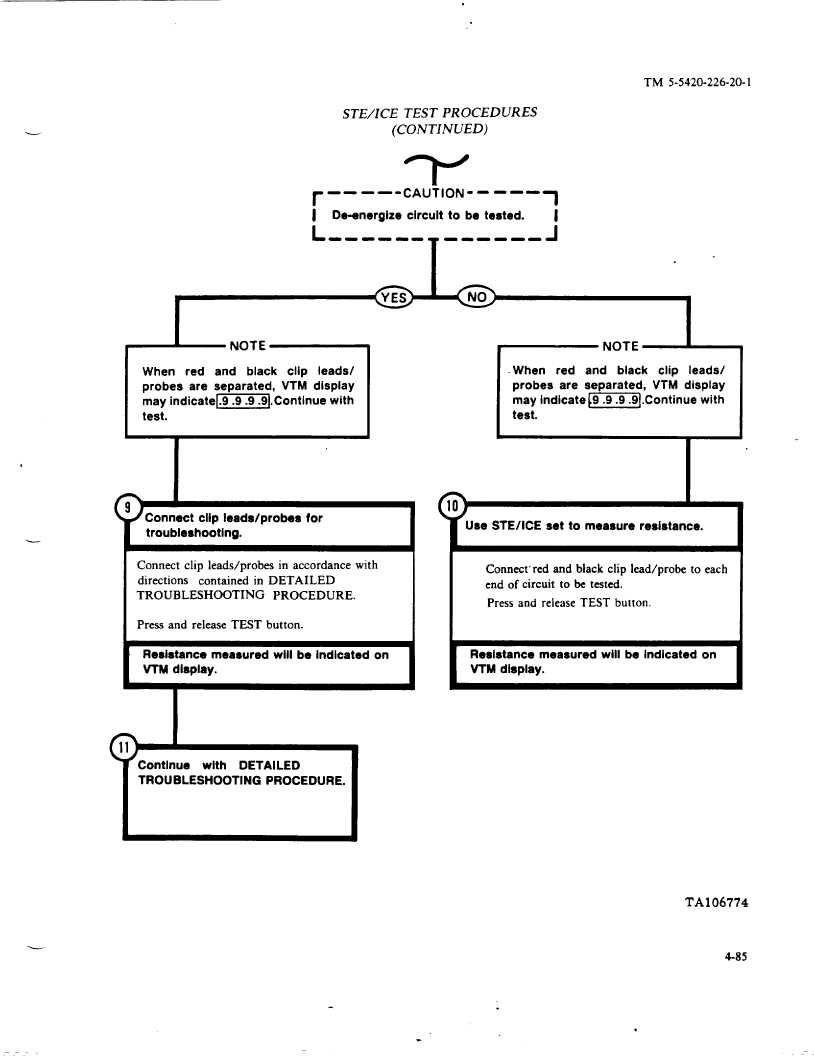
STE/lCE
TEST PROCEDURES
(CONTINUED)
r
---
—.CAUT10N-----
1
I De-energize circuit to be tested.
I
L ------
------
- J
When
red
snd
black
clip
leads/
probes are separated, VTM display
may indicate[~].
Continue with
test.
r
NOTE ~
When
red
and
black
clip
ieads/
probes are separated,
VTM display
may indicate -].
Continue with
test.
Connect CIIP leads/probes
for
troubleshooting,
(
Connect clip leads/probes
in accordance
with
directions
contained
in DETAILED
TROUBLESHOOTING
PROCEDURE.
I
Press and release TEST button.
I
L
Resistance measured will be Indicated on
VTM display.
Continue
with
DETAILED
TROUBLESHOOTING
PROCEDURE.
TUse STE/iCE set to measure resistance.
I
Connect’ red and black clip lead/probe
to each
end of circuit to be tested.
Press and release TEST button.
Resistance measured will be indicated on
VTM display.
TA106774
4-85
.