TM 5-5420-226-20-1
(
SIMPLIFIED
TEST
EQUIPMENT/lNTERNAL
COMBUSTION
ENGINE
(STE/lCE)
SET
(Continued)
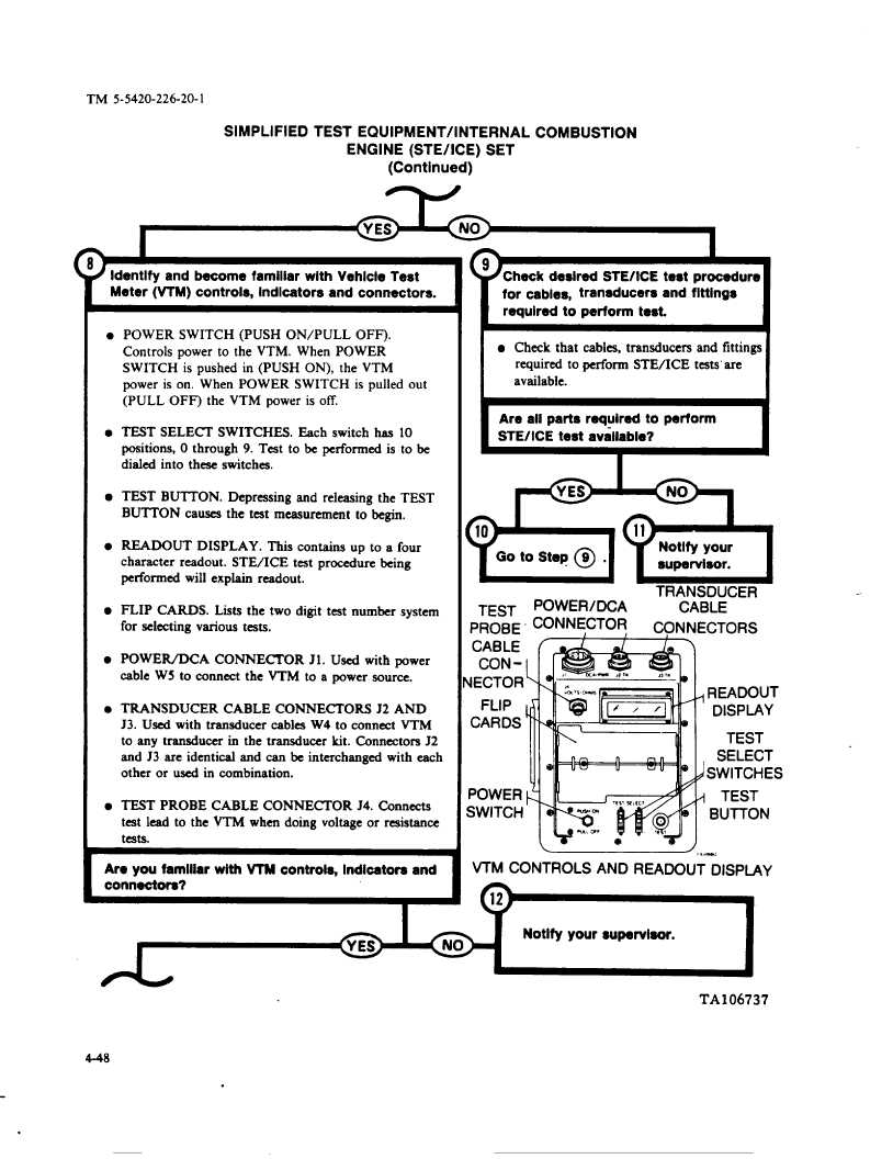
Identify and become famiiiar with Vehicle Test
Meter (vTM) controis, indicators and connectors.
l POWER SWITCH (PUSH ON/PULL
OFF).
Controls
power to the VTM. When POWER
SWITCH
is pushed in (PUSH ON), the VTM
power is on. When POWER
SWITCH
is pulled out
(PULL OFF) the VTM power is off.
.
TEST SELE~
SWITCHES.
Each switch has 10
positions, O through
9. Test to be performed
is to be
dialed into these switches
l TEST BUTTON.
Depressing
and releasing the TEST
BUTTON
causes the test measurement
to begin.
.
READOUT
DISPLAY.
This contains
up to a four
character
readout.
STE/ICE
test procedure
being
performed
will explain readout.
l FLIP CARDS.
Lista the two digit test number system
for seiecting various teats.
.
POWER/DCA
CONNECTOR
J 1. Used with power
cable W 5 to connect the VTM to a power source.
l TRANSDUCER
CABLE CONNECTORS
J2 AND
J3. Used with transducer
cables W4 to connect VTM
to any transducer
in the transducer
kit. Connectors
J2
and J3 are identical and can be interchanged
with each
other or used in combination.
l TEST PROBE CABLE CONNECTOR
J4. Connects
test lead to the VTM when doing voltage or resistance
te9ts.
Are you famiiiar with WW controia, indicators and
connectom?
H
(#Checkdesired STE/lCE test procedure
for cabies, transducers and fittin9$
required to perform test.
I
l Check that cables, transducers
and fittings
required to perform STE/ICE
tests” are
available.
I
Are aii parta required to perform
STE/iCE test avaiiabie?
I
H11Notify your
supervisor.
TRANSDUCER
TEST
pOwER/DCA
CABLE
PROBE
CTORS
CABLE
CON-
lECTOR
FLIP
READOUT
CARDS
DISPIAY
TEST
SELECT
SWITCHES
POWER
TEST
SWITCH
BUITON
~,,,,m
VTM CONTROLS AND READOUT DISPIAY
12
/
I
-o
Notify your supervisor.
No
/
TA106737
4-48
.