TM 5-2350-262-20-2
Change 3 4-415
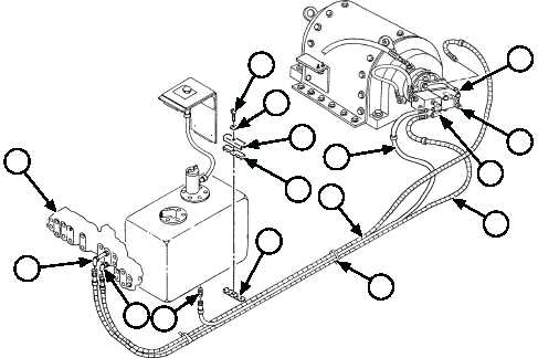
A Route hoses (1), (2) and (3) in appropriate
locations for installation.
B Install hoses (1) and (2) on elbows (14) and (15)
at directional control valve bank (16).
C Connect hoses (1) and (2) to elbows (4) and (5)
at winch motor (7).
D Connect hose (3) to elbow (5) at hydraulic motor
and adapter (6) at bottom of hydraulic reservoir.
INSTALLATION
Note
• Refer to hose and tube marker band
identification (p 3-101) for specific hose
routing.
• Class III leaks can occur if hydraulic lines
and fittings are improperly installed or not
fully servicable. Refer to page 2-29 when
replacing or repairing hydraulic system
components. Always inspect suspension
system lines, fittings, and packings for
servicablity before installation.
• Use two wrenches to connect hoses to
fittings.
E Secure hoses (1), (2) and (3) to bracket (11) with
hose bracket (12), retain strap (13), washer
(10), and new self-locking screw (9).
F
Secure hoses (1), (2) and (3) with tiedown
straps (8).
FOLLOW-ON TASKS:
• Install rear floor plates (p 4-360).
• Install hull access covers (p 4-375).
• Service hydraulic tank (TM 5-2350-262-10).
• Retract ejector (TM 5-2350-262-10).
16
14
15
13
12
11
10
9
4
7
5
2
1
8
3
6