

TM 9-2350-222-34-1
MAGNETIC CLUTCH ADJUSTMENT (Sheet 2 of 2)
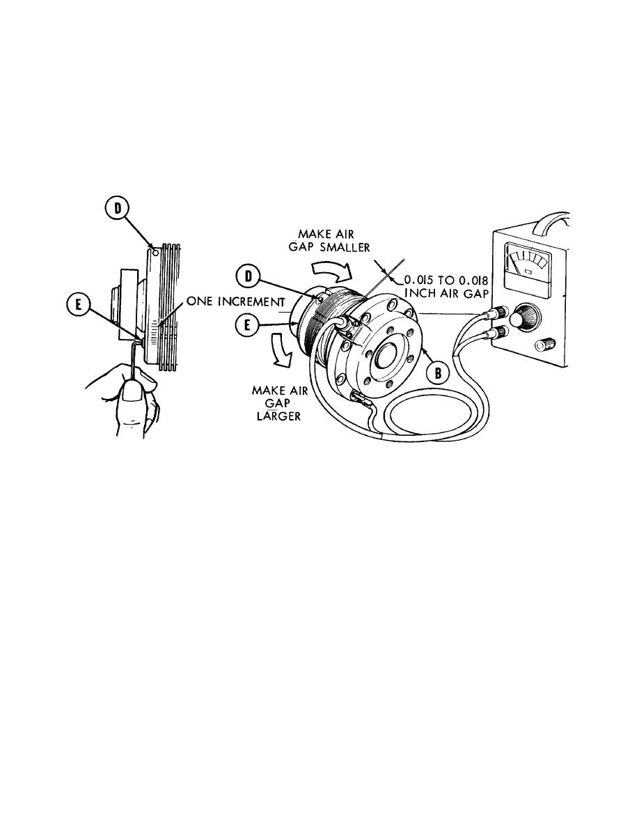
5. Turn off power supply.
6. Using socket head screw key, loosen screw (D).
NOTE
Make a pencil mark as an index mark for ease of counting increments.
7. Using socket head screw key, turn adjusting nut
(E) one increment in direction indicated for each
0.001 inch necessary to provide air gap
average of .015 to .018.
8. Using socket head screw key, tighten screw
(D).
9. Perform steps 2 through 8 until average of the
four thickness gage readings is 0.015 to 0.018
inch.
10. Disconnect power supply from magnet body
half (B).
11. Install magnetic clutch (TM 9-2350-222-20-1).
End of Task
TA130882
12-59

