

TM 9-2350-222-34-1
ACCELERATOR LINKAGE ASSEMBLY REPLACEMENT (Sheet 5 of 5)
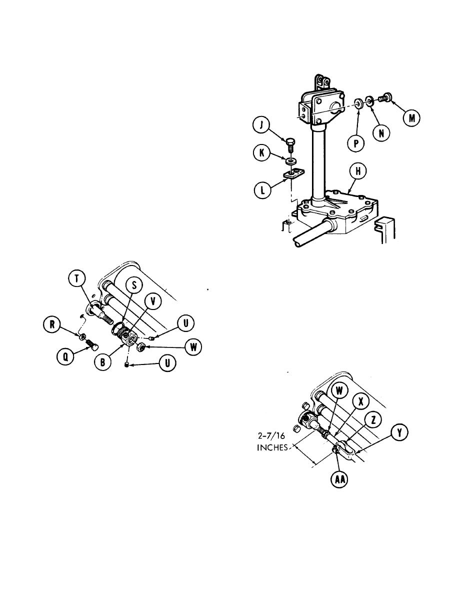
6. Aline two holes in base of accelerator linkage
assembly (H) with two mounting holes on floor of
engine compartment.
7. Using 9/16 inch socket, install and secure two
screws (J), lockwashers (K), and plate (L) to
secure housing to floor.
8. Using 9/16 inch socket, install and secure two
screws (M), lockwashers (N) and flat washers
(P) to secure upper housing to bulkhead.
9. Using 9/16 inch socket, install and secure three
screws (Q) and lockwashers to secure tube
assembly of linkage assembly to bulkhead.
10. Install washer (S) and nut (B) over shaft (T).
Using 1-7/16 inch wrench, tighten nut (B).
11. Using allen wrench, install two setscrews (U) into
two holes in nut, leaving the uppermost hole
empty for grease fitting.
12. Using 3/8 inch wrench, install grease fitting (V)
into uppermost hole in nut (B).
13. Using inch wrench, install nut (W). Screw nut
onto shaft (T) until it bottoms.
14. Using inch wrench, install rod end (X) onto
shaft. Install rod end until measurement of 2-
7/16 inches is attained between center of rod
and shoulder of shaft as shown.
15. Position rod end (X) into clevis (Y) and install pin
(Z).
16. Using pliers, install new cotter pin (AA) through
end of pin. Bend cotter pin to prevent it from
falling out.
17. Using inch wrench, tighten nut (W) up against
rod end (X).
18. Install powerplant (TM 9-2350-222-20).
TA130560
End of Task
4-102

