

TM 9-2350-222-20-2-3-2
IR PERISCOPE SPARE HEAD STOWAGE BOX INSTALLATION PROCEDURE
15-3.
(CONT)
FRAME 1
Procedure
Step
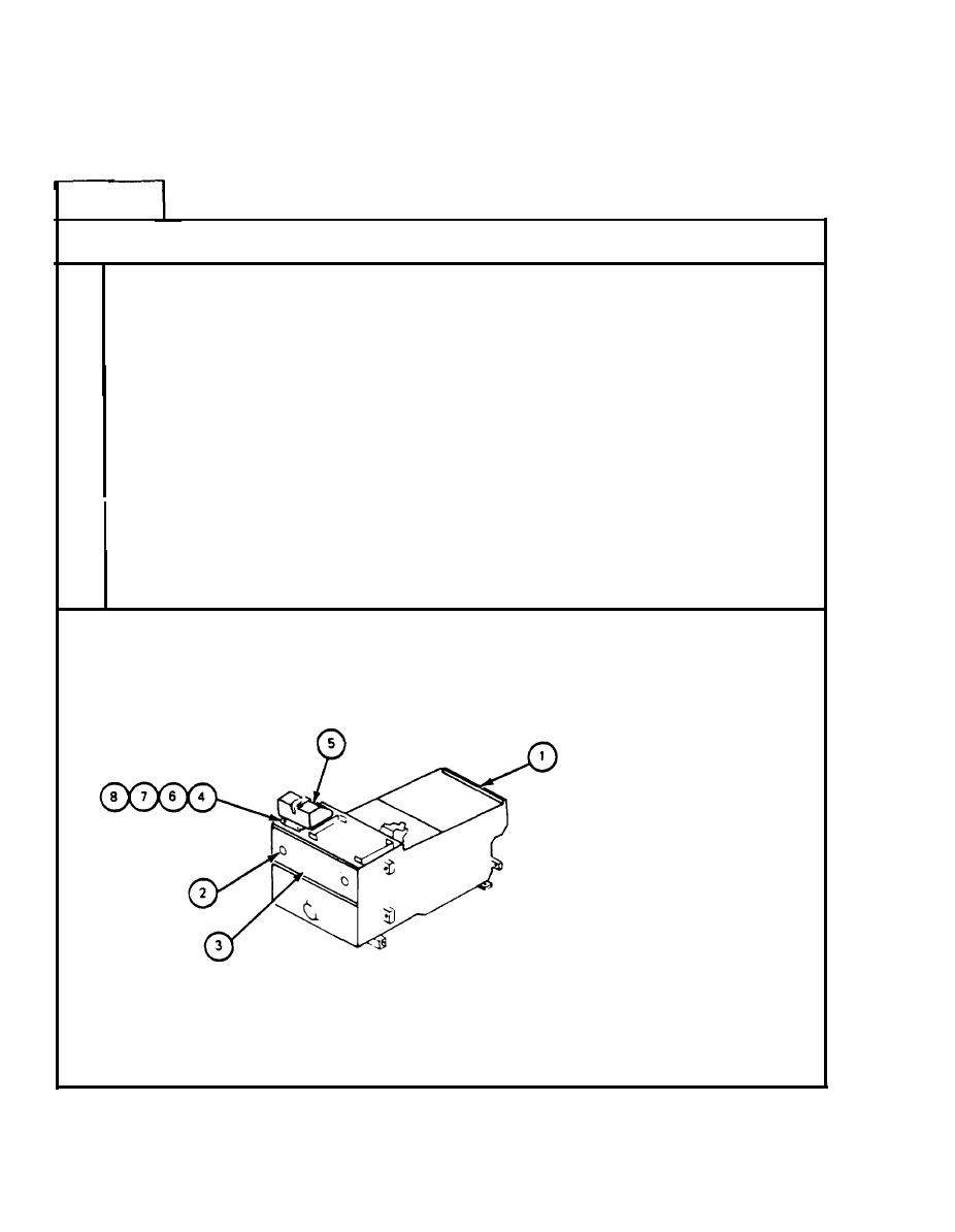
1.
Traverse turret until periscope stowage box (1) can be reached from driver's compartment
(TM-10).
2.
Set turret traverse lock to LOCKED (TM- 10).
Open two latches (2) and open door (3).
3.
NOTE
Put in four screws (4) with screw head inside periscope
stowage box (1).
4.
Using screwdriver and wrench, attach IR periscope spare head stowage box (5) to
periscope stowage box (1) with four screws (4), `four lockwashers (6). four flat washers
(7), and four nuts (8). Torque four nuts (8) to between 48 and 60 inch-pounds.
5.
Close door (3) of stowage box (1).
END OF TASK
Para 15-3 Cont
15-4

