

TM 9-2350-222-20-1-5
CONTROL VALVE ASSEMBLY REPLACEMENT (Sheet 10 of 12)
NOTE
Handle (AD) must be turned fully
before doing
counterclockwise
step 19.
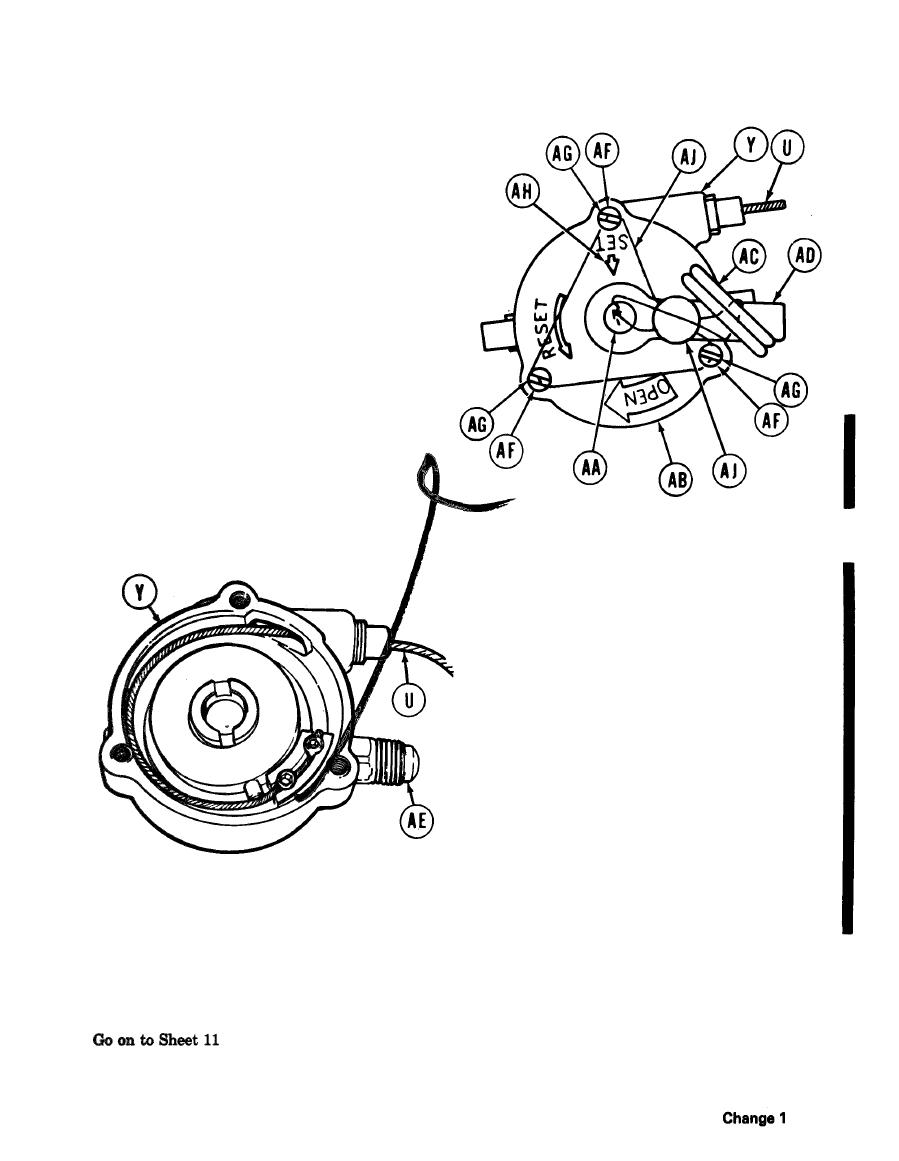
19. Aline arrow on shaft (AA) with SET on cover
(AB) and install safety pin (AC) through handle
(AD) and cover (AB).
20. Position handle (AD) over adapter (AE) and
install cover (AB) onto housing (Y) with screws
(AF) and washers (AG). Using screwdriver,
tighten screws (AF).
21. Remove safety (AC). Check operation of
valve by releasing with cable and resetting
with handle. Release and reset several
times. Verify that pin in bottom of valve
extends and retracts each time.
NOTE
Use safety pin, nail, or similar
device to turn shaft in step 22.
22. Turn shaft counterclockwise and reset valve by alining-- arrow on shaft (AA) with SET arrow (AH) on
valve rover (AB). Reinstall safety pin (AC).
23.
Using slip joint pliers, install new lead seal (AJ) through cover screws (AF) and safety pin (AC).
TA253870

