

TM 9-2350-222-20-1-4
STEERING CONTROL LINKAGE ADJUSTMENT (Sheet 11 of 13)
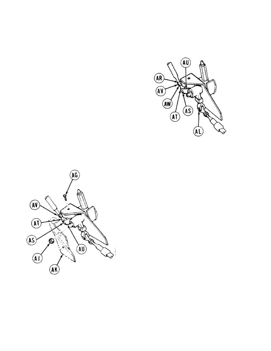
65.
Using torque wrench with socket, tighten
screw (AL) to 15-20 lb-ft (20-27 N-m).
Check threads at end of steering rod (AR) to
66.
make sure threads are past check hole.
If threads are not showing, using 9/16 inch
67.
wrench, remove screw (AS).
Remove steering rod end bearing (AT) from
68.
clevis (AU).
Using 9/16 inch wrench, loosen jamnut (AV).
69.
Using 9/16 inch wrench on steering rod end
70.
bearing flats (AW), turn counterclockwise or
clockwise until threads are showing past check
hole.
LEFT SIDE OF HULL
(TO REAR OF FUEL TANK)
71. Place steering rod end bearing (AT) into
clevis (AU).
72. Using 9/16 inch wrench, install screw (AS).
73. Using crowfoot wrench, adapter, and
torque wrench, tighten jamnut (AV) to
15-20 lb-ft (20-27 N-m).
74. Using torque wrench with socket, tighten
screw (AS) to 15-20 lb-ft (20-27 N-m).
75. Using fingers, remove nut (AJ).
76. Position plate (AK) to linkage assembly.
77. Using 7/16 inch wrench, install screw (AG).
LEFT SIDE OF HULL (TO REAR OF FUEL TANK)
Go on to Sheet 12
15-12 Change 5

