

TM 9-2350-222-20-1-4
PARKING BRAKE CONTROL ASSEMBLY AND LINKAGE REPLACEMENT
(DRIVER'S STATION) (Sheet 6 of 10)
Attach 15 foot piece of safety wire (Item 61, Appendix D) to end of control assembly located inside
22.
driver's station. Make sure one end of wire is wrapped tight several times around end of control
assembly, and other end is secured to a wrench or other moveable object which will not allow free
end of wire to pass through bulkhead opening.
NOTE
Two persons are required to remove control assembly from
vehicle; one person inside turret and one person inside engine
compartment.
23.
Person in engine compartment grasps control assembly with both hands and pulls toward rear of
vehicle, while person inside turret makes sure control assembly and wire feed through hole in
bulkhead and tube. Insure that retainer is removed from control assembly as control assembly is
being pulled through bulkhead.
24,
When control assembly is clear of tube located behind fuel tank, person in engine compartment
disconnects wire from control assembly and removes control assembly from vehicle. Make sure
wire is secured to a wrench or other moveable object so that wire will remain in tube for
installation of new control assembly.
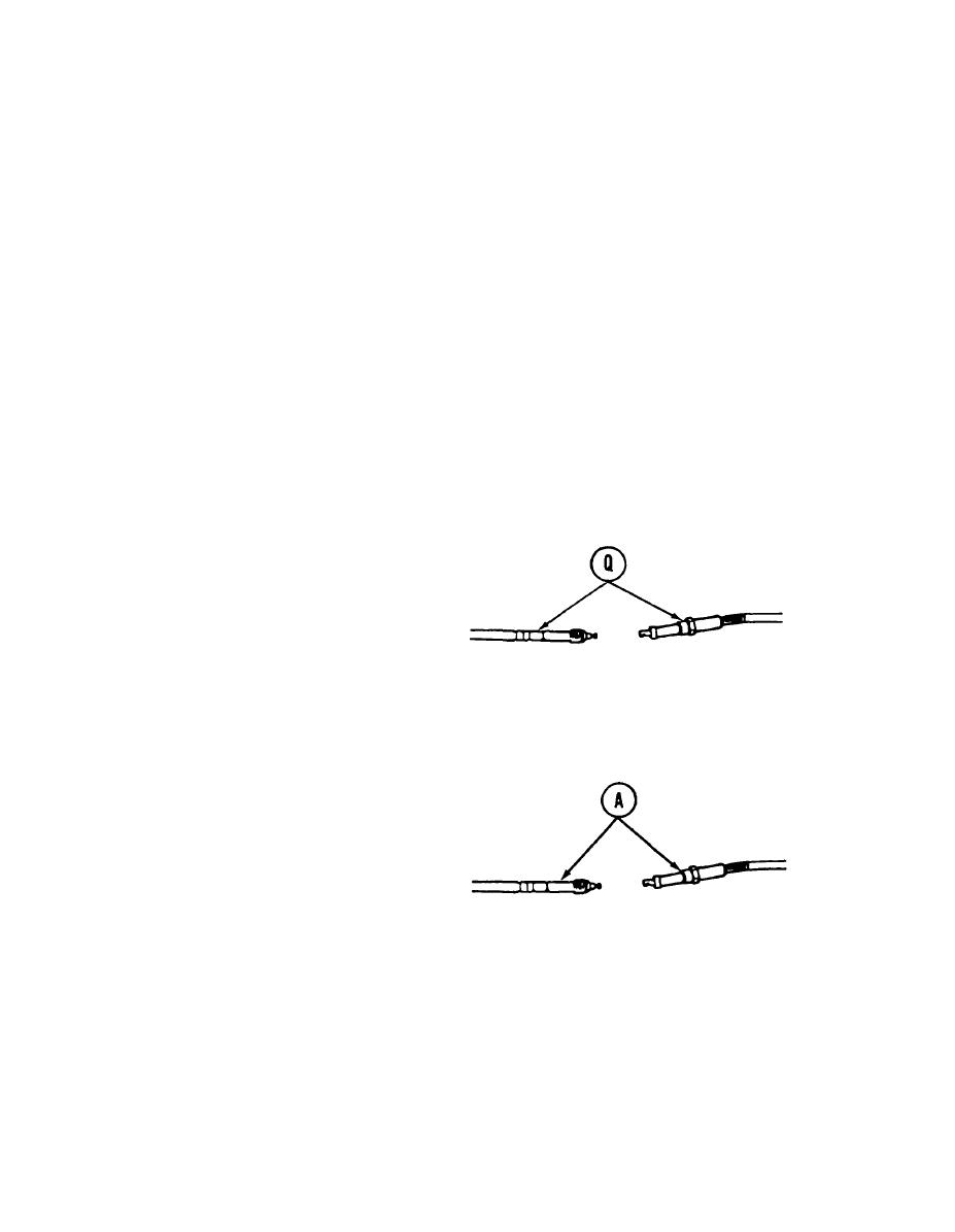
25
Using adjustable wrench to hold control
assembly (Q), use 7/8 inch wrench to loosen
connector on control assembly (Q). Separate
ccntrol assembly (Q) into two pieces.
CLEANING AND INSPECTION:
1.
Clean all parts, using dry cleaning solvent (Item 54, Appendix D).
2.
Inspect all mounting hardware for cracks in brackets, worn pivot pins, and damaged threads on
screws and nuts. Replace any damaged parts.
INSTALLATION:
NOTE
Step 1 applies only to two-piece
cable.
1.
Using adjustable wrench and 7/8 inch wrench, connect the two pieces of control assembly (A)
together. Using torque wrench and 7/8 inch crow foot, tighten connector on control assembly (A)
to 35-50 lb-in (9-13 N.m).
Go on to Sheet 7
TA140415
13-110

