

TM 9-2350-222-20-1-4
PARKING BRAKE PAWL AND BELLCRANK ADJUSTMENT (Sheet 4 of 9)
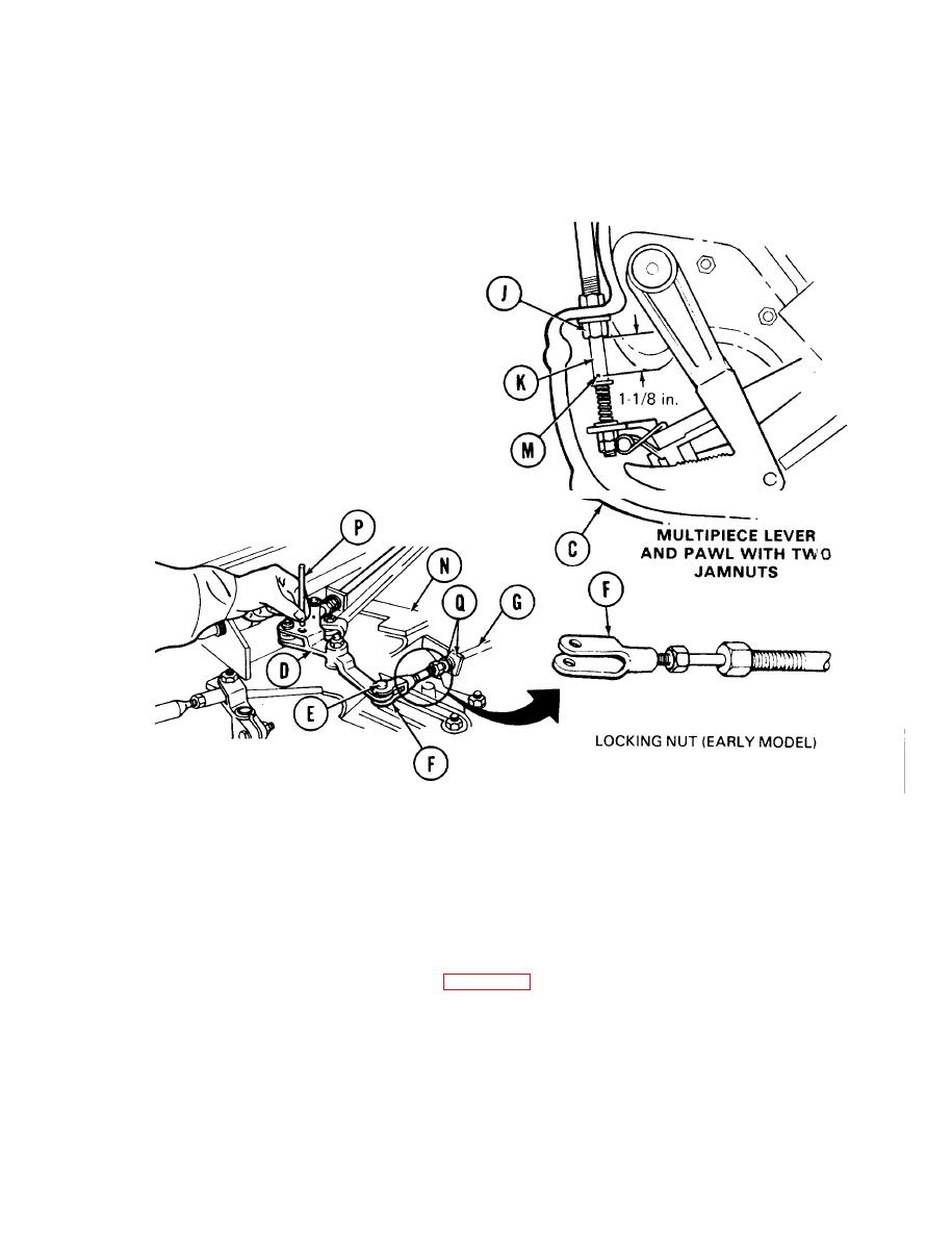
6.
Push/pull cable (K) until 1-1/8 inch gage
block fits between cotter pin (M) and sleeve
nut (J). (15/ 16 gage block for one-piece lever
and pawl.)
7.
At top of transmission, rotate bellcrank as-
sembly (D) to aline holes in bellcrank (D and
bracket (N). Insert 1/8 inch locating pin (P)
through holes in bellcrank (D) and bracket
(N).
NOTE
On early model cables use a 9/16
inch wrench to back off a lock-
ing nut before you can adjust cle-
vis (F). After clevis (F) is adjusted
tighten locking nut against clevis
(F).
8.
Using two 15/16 inch wrenches, loosen two nuts (Q) and adjust control assembly (G) until clevis pin (E)
slides freely in the respective holes. If clevis pin (E) binds at bellcrank, adjust clevis (F) unit] bind no
longer occurs.
9.
Using two 15/16 inch wrenches, tighten nuts (Q), install clevis pin (E) and using pliers, install washer
and new cotter pin on clevis pin (E).
Remove gage block from side housing assembly (C).
10.
11.
Remove locating pin (P). Rotate bellcrank (D) left and right to check for free movement . If bellcrank
moves freely continue adjustment, refer to page 13-18.2. If bellcrank binds, replace control cable
assembly (Page 13-84).
Go on to Sheet 5
TA253419
Change 1 13-18.1

