

TM 9-2350-222-20-1-4
SHIFT LINKAGE ADJUSTMENT (Sheet 20 of 20)
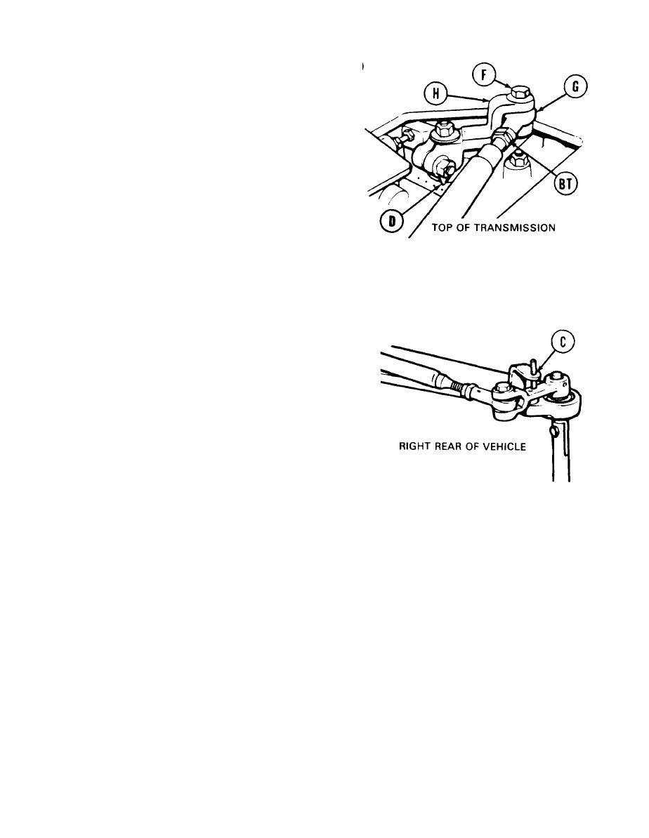
NOTE
I t may be necessary to move
p o s i t i o n indicator (D) to most
rear positioned dot to adjust rod
end, and then back to most for-
ward positioned dot to check
adjustment in step 155.
155. Using 9/16 inch wrench, adjust shifting rod
bearing end (G) by turning clockwise or
counterclockwise until screw (F) drops freely
through clevis (H) and shifting rod bearing
end (G).
156. Using 9/16 inch wrench, install screw (F)
through clevis (H) and shifting rod bearing
end (G).
157. Using crowfoot and torque wrenches, tighten
jamnut (BT) to 15-20 lb-ft (20-27 N-m).
158. Remove locating pin from alinement hole (C).
159. Using 9/16 inch socket and torque wrench, tighten screw (F) to 15-20 lb-ft (20-27 N.m).
160. Install ammunition rack (page 17-9).
161. Check shifting pattern response (TM 9-2350-222-10). If transmission still does not shift correctly,
notify support maintenance. If transmission does shift correctly, go on to step 162.
162. Install top deck (page 16-23).
163. Install transmission shroud (page 9-23).
TA253378
End of Task
Change 1 11-21

