

TM 9-2350-222-20-1-4
MASTER CONTROL PANEL REPAIR (Sheet 5 of 65)
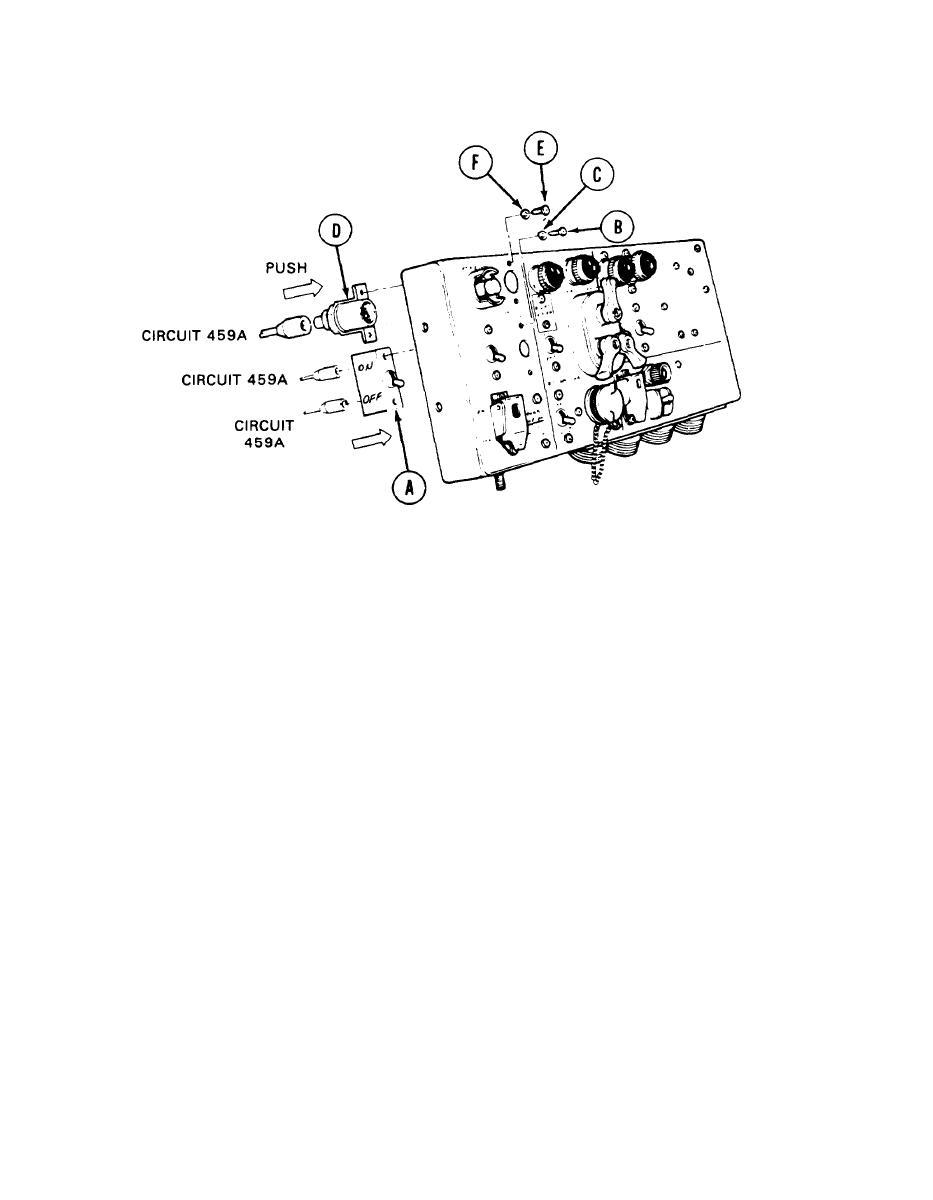
Master Battery Switch and Indicator Light Replacement (Sheet 3 of 4)
INSTALLATION:
1.
Apply silicone compound (Item 32, Appendix D) to two male connectors for switch (A) (circuits 459
and 459A).
2.
Using fingers, install two connectors (circuits 459 and 459A) to rear of switch (A) by pushing in.
NOTE
Before installing switch (A), make sure switch (A) is in OFF
position. If OFF position is not marked on switch (A), use
multimeter to make sure switch (A) is in OFF position.
Place switch (A) in position on panel.
3.
Using screwdriver, install two screws (B) and new lockwashers (C).
4.
5.
Apply silicone compound to connector on base assembly (D).
6.
Using fingers, install connector (circuit 459A) to rear of base assembly (D) by pushing in.
7.
Place base assembly (D) in position on panel.
8.
Using screwdriver, install two screws (E) and new lockwashers (F) securing base assembly (D) to
panel.
Go on to Sheet 4
TA139615
10-59

