

TM 9-2350-222-20-1-3
TURBOCHARGER SHROUDS REPLACEMENT (Sheet 6 of 6)
Upper Shroud Replacement (Sheet 1 of 1)
TOOLS:
1/2 in. combination box and open end wrench
1/2 in. socket with 1/2 in. drive
5 in. extension with 1/2 in. drive
Ratchet with 1/2 in. drive
SUPPLIES: Self-locking nut (MS21044N5)
Remove powerplant (page 5-1)
PRELIMINARY PROCEDURES:
Remove rear engine shroud support (page 9-4)
NOTE
Procedures for replacement of the left or right turbocharger
shrouds are similar. Procedures for the left side are shown.
REMOVAL:
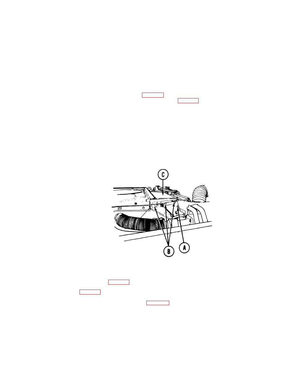
1.
Using 1/2 inch socket with extension and 1/2 inch wrench, remove screw and self-locking nut (A).
Throw self-locking nut (A) away.
2.
Using 1/2 inch socket, remove three screws (B).
Remove upper shroud (C).
3.
INSTALLATION:
Position upper shroud (C) in place.
1.
2.
Install three screws (B).
3. " Install screw and new self-locking nut (A).
Using 1/2 inch socket with extension and 1/2 inch wrench, tighten screws (A) and (B).
4.
Install rear engine shroud support (page 9-5).
5.
Install engine shroud (page 9-3).
6.
Install 2A powerplant (page 5-14) or 2D Powerplant (page 5-37).
7.
End of Task
TA140254
9-18

