

TM9-2350-222-20-1-3
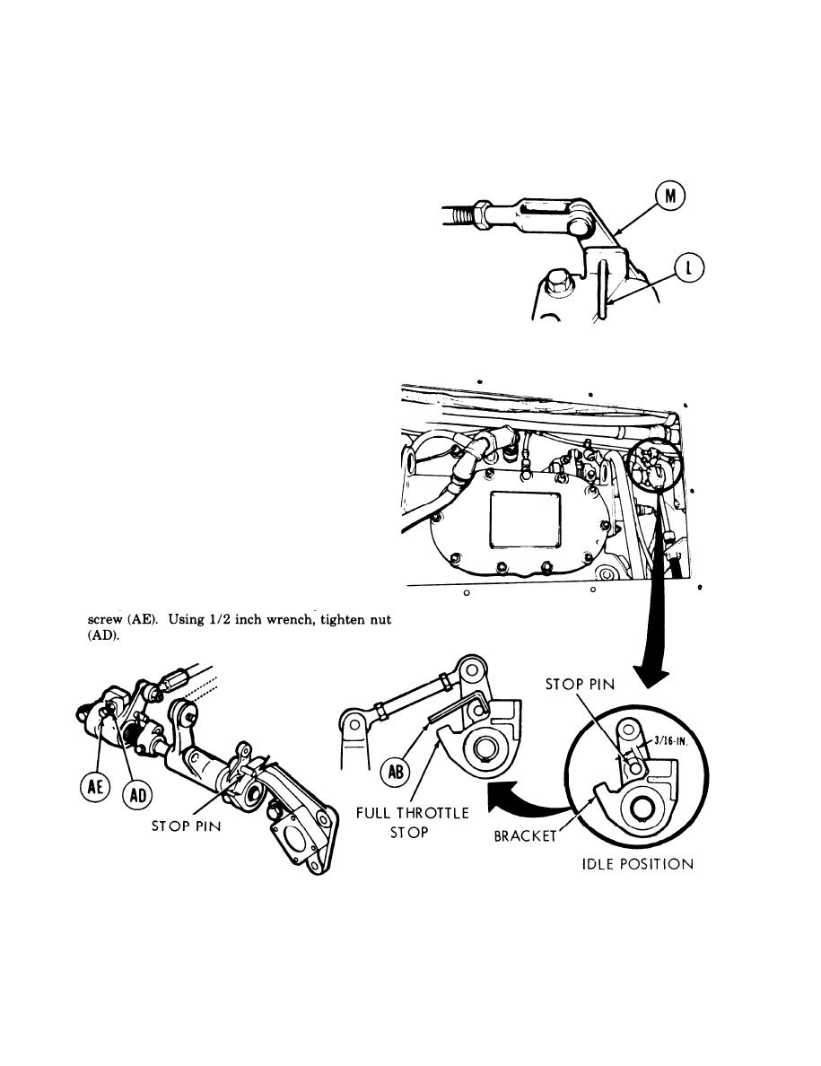
ACCELERATOR LINKAGE ADJUSTMENT (Sheet 6 of 8)
Traverse turret to position gun tube to rear for
35.
entry to driver's station (TM 9-2350-222-10).
Remove locating pin (L) from remote control
36.
lever (M).
Traverse turret to position gun tube to front for
37.
access to engine compartment (TM
9-2350-222-10).
Have one person in driver's station ready to
38.
start engine and watch tachometer while the
other person measures accelerator travel at
engine.
Start engine (TM 9-2350-222-10).
39.
40.
Using fabricated go/no go gage (AB) (Figure
F-3, Appendix F), increase far at least 3/16
inch clearance at idle speed 700 to 750 rpm.
If idle adjustment is necessary, perform steps
41 and 42.
If adjustment is not necessary,
go on to step 43.
41.
Using 1/2 inch wrench, loosen nut (AD). Adjust
idle adjustment screw (AE) to the requirements
of step 40. If requirements are met, go to step
42; if requirements cannot be met, notify
support maintenance.
Using 1/2 inch wrench, hold idle adjustment
42.
Go on to Sheet 7
TA141448
7-420

