

TM9-2350-222-20-1-3
ACCELERATOR LINKAGE ADJUSTMENT (Sheet 4 of 8)
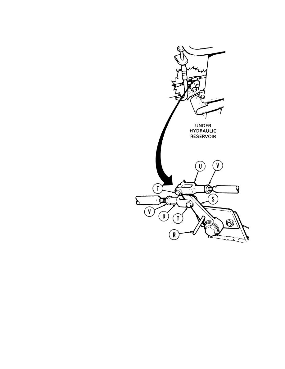
19.
Insert 1/8 inch diameter pin (R) through
alinement hole of lever assembly (S). If locating
pin (R) cannot be inserted, perform steps 20
thru 25. If locating pin can be inserted, go to
step 25.
20.
Using pliers, remove two cotter pins and pins
(T). Throw cotter pins away.
21.
Using 1/2 inch wrench to hold each clevis (U),
use 1/2 inch wrench to loosen each nut (V).
22.
Position lever assembly (S) so that locating pin
(R) can be inserted.
23.
Turn two clevises (U) until two pins (T) slip
freely into lever assembly (S). Using pliers,
install two new cotter pins through pins (T).
24.
Using 1/2 inch wrench to hold each clevis (U),
use 1/2 inch wrench to tighten each nut (V).
25.
Remove locating pin (R).
Go on to Sheet 5
TA141446
7-418

