

TM9-2350-222-20-1-3
FUEL PUMP-TO-FUEL-WATER SEPARATOR HOSE ASSEMBLY REPLACEMENT
(Sheet 5 of 5)
3.
Set FUEL PUMPS switch to ON.
4.
Set MASTER BATTERY switch to ON.
5.
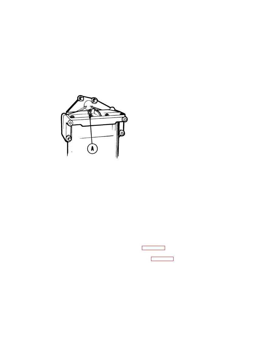
Watch fuel-water separator bleed cap (A) until air release (bubbles) appears, then set MASTER
BATTERY switch to OFF.
NOTE
It may be necessary to perform
steps 5 and 6 several times until
a constant fuel flow (no bubbles)
from the bleed cap (A) is
observed.
T w o persons are
required to perform steps 3, 4,
and 6.
6.
Wait about one minute and repeat step 4 until a constant free flow is observed at bleed cap (A).
7.
Using 7/16 inch wrench, turn bleed cap (A) clockwise until snug.
8.
Check for leaks. Tighten or replace components as necessary.
9.
(2D engine only). Perform operational check of automatic drain (page 7-269).
10. Set MASTER BATTERY switch to OFF.
11. Disconnect engine from powerplant ground hop (page 5-62).
12. Install 2A powerplant (page 5-14) or 2D powerplant (page 5-37).
End of Task
TA148882
7-303

