

TM9-2350-222-20-1-3
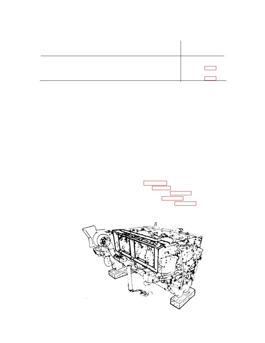
POWERPLANT LEFT BANK OIL COOLER FRAME AND BRACKETS REPLACEMENT
(2D ENGINE) (Sheet 1 of 9)
PROCEDURE INDEX
PAGE
PROCEDURE
Removal
Installation
Alining punch
TOOLS: Ratchet with 1/2 in. drive
1/2 in. combination box and
5 in. extension with 1/2 in. drive
open end wrench
1/2 in. socket with 1/2 in. drive
3/8 in, combination box and
5/8 in. socket with 1/2 in. drive
open end wrench
9/16 in, socket with 1/2 in. drive
9/16 in. combination box and
11/16 in. socket with 1/2 in. drive
open end wrench
4 in.. flat-tip screwdriver
SUPPLIES: Lockwasher (7410218) (4 required)
Self-locking nut (MS21045-4) (4 required)
Self-locking nut (MS21045-6) (9 required)
Self-locking nut (8764639)
Self-locking nut (MS21044N5) (12 required)
Self-locking nut (MS21045-5)
Self-locking nut (MS21045-7) (6 required)
PERSONNEL: TWO
PRELIMINARY PROCEDURES: Remove powerplant (page 5-25)
Remove engine shroud (page 9-2)
Remove centrifugal fan housing (page 9-59)
Remove engine cooling fans (page 9-48)
Remove engine cooling fan shroud (page 9-52)
Remove engine access covers (left bank) (page 6-90)
Remove engine left oil cooler (page 6-130)
Remove transmission left oil cooler (page 6-146)
TA139477
Go on to Sheet 2
6-109

