

TM 9-2350-222-20-1-3
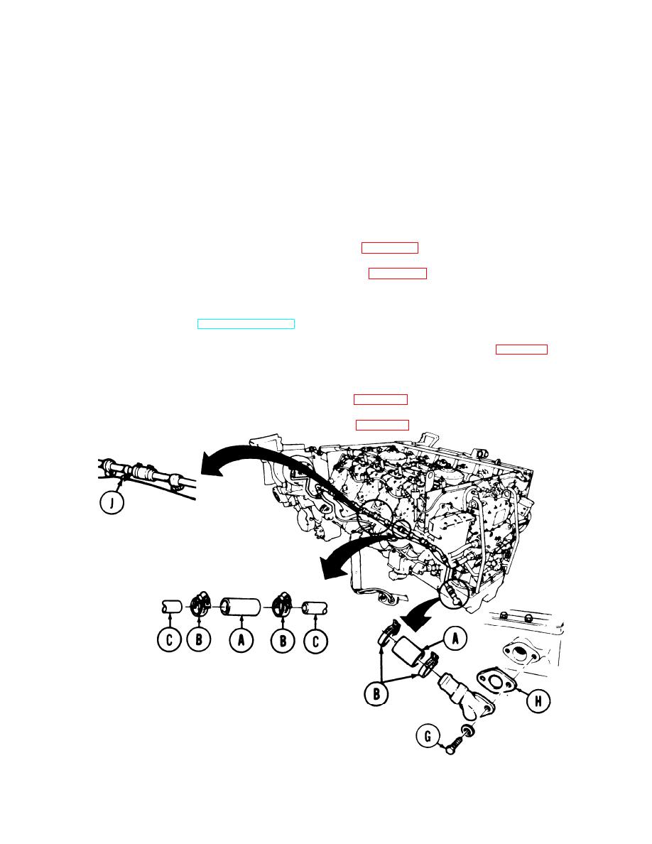
CYLINDER HEAD AND OIL PAN DRAIN TUBES (LEFT AND RIGHT) REPLACEMENT
(Sheet 4 of 4)
Position two bolts and new lockwashers (G) through lower drain tube end and place new gasket
8.
(H) over bolts.
9.
Using 1/2 inch socket, tighten two bolts and lockwashers (G) to engine.
10.
Using screwdriver, tighten 16 clamps (B) on hoses on each end of lower drain lines assembly.
11.
Holding nut with 3/8 inch wrench and using screwdriver, connect four fuel line clamps (J) to oil
drain line.
Install left oil cooler frame and brackets (2D engine) (page 6-114) (as required).
12.
Install right oil cooler frame and brackets (2D engine) (page 6-104) (as required).
13.
14.
Install powerplant (2A engine) oil cooler frame and brackets (page 6-97).
15.
Replenish engine oil (LO 9-2350-222-12).
16.
Connect powerplant test (ground hop) equipment (Item 30, Chapter 3, Section I) (page 5-49).
17.
Start engine and check for leaks.
18.
Disconnect powerplant test (ground hop) equipment (page 5-62).
19.
Install 2A powerplant (page 5-14) or 2D powerplant (page 5-37).
End of Task
TA139425
6-57

