.
-—
(
TM 5-5420-226-20-1
STE/ZCE TES.T PROCEDURES
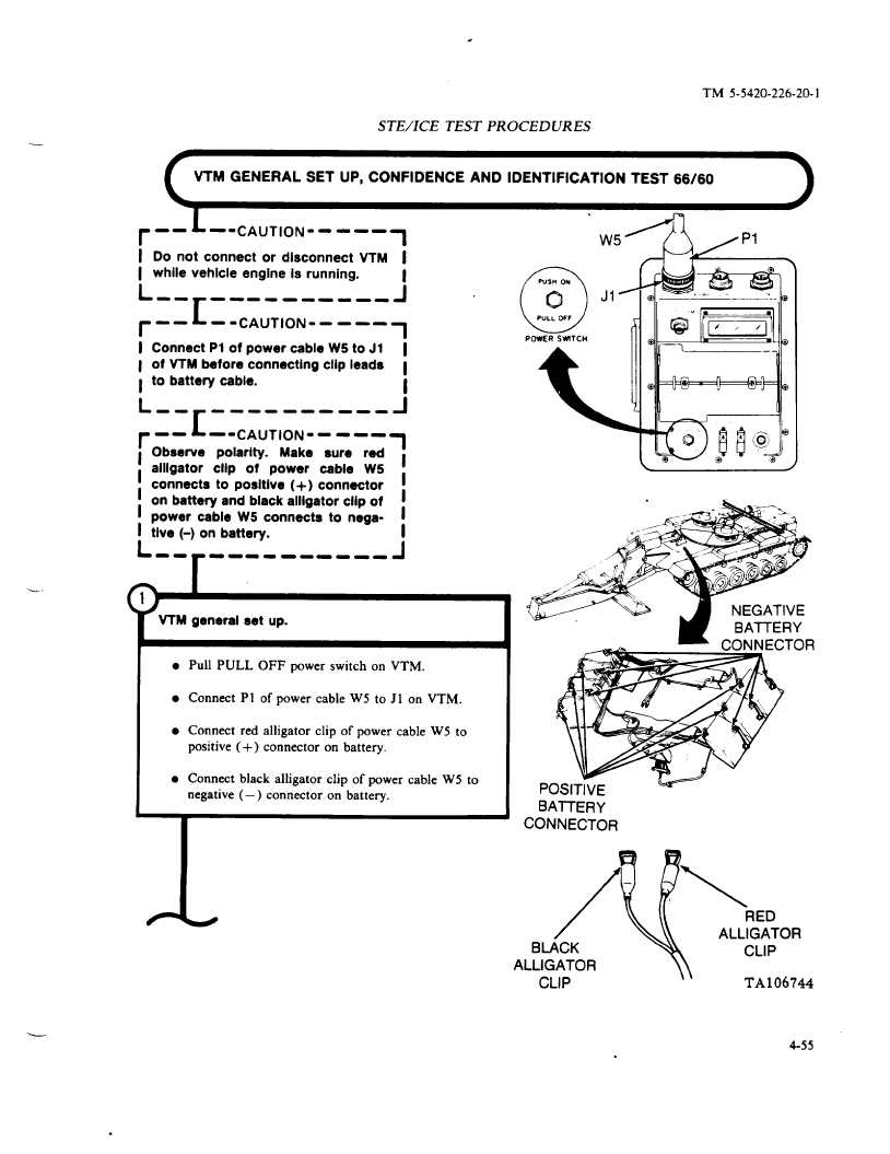
VTM GENERAL
SET UP, CONFIDENCE
AND IDENTIFICATION
TEST 66/60
.
r
-- L-CAUTION.----,
I
Do not connect or disconnect VTM
I
I while vehlcie engine is running.
L -.
[
-----
-----
~
r
--
--CAUTION.
----
1
i Connect PI of power cable W5 to J1 I
1 of VTM before connecting clip leads
1
1 to battery cable.
I
L
~-------___J
--
r~
--
‘-CAUTION
-----l
I
I
I
I
1
L -.
r
------
----
a
Observe
polarity.
Make
sure
red
alligator
CIIP of
power
cable
W5
i
connects to positive (+)
connector
on battery and black alligator clip of
!
power cable W5 connects to nega-
I
tive (-) on battery.
I
i
VTM general set up.
l Pull PULL OFF power switch on VTM.
l Connect PI of power cable W5 to J 1 on VTM.
l Connect red alligator clip of power cable W5 to
positive (+)
connector
on battery,
l Connect black alligator clip of power cable W5 to
negative ( —) connector
on battery.
ALLIGATOR
CLIP
I\
TA106744
4-55